Crushing and mining machinery
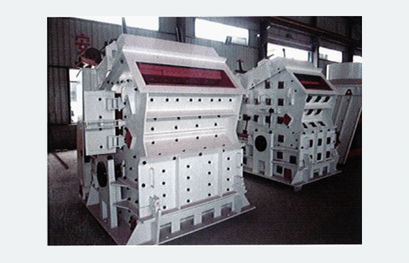
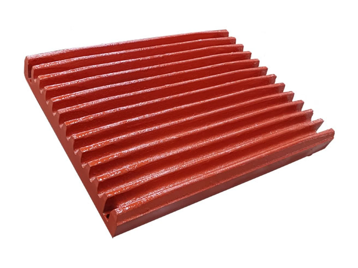
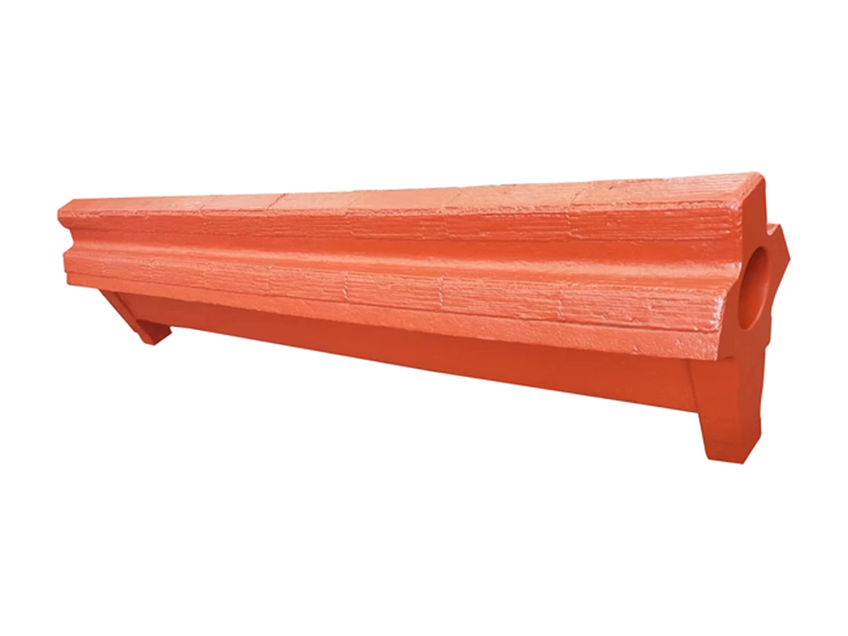
The crusher view illustrates wear-intensive machinery service. Match the liner form, fixing arrangement, feed material and impact conditions.
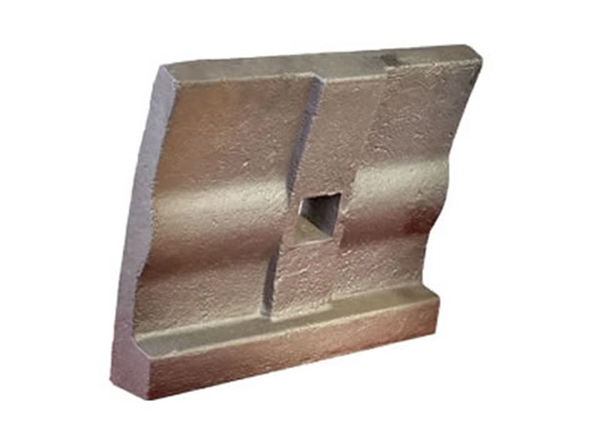
Mining and metallurgical machinery parts provide contact protection, material guidance and local support in heavy-duty equipment, including wear plates, liners and shaped metal components. Selection should relate installation position, fixing arrangement, contacting material, impact and temperature to geometry and material selection. Distinguish consumable working surfaces from load-bearing interfaces when describing the part. A photograph of the external shape alone does not establish function, loading or compatibility with a particular machine position.
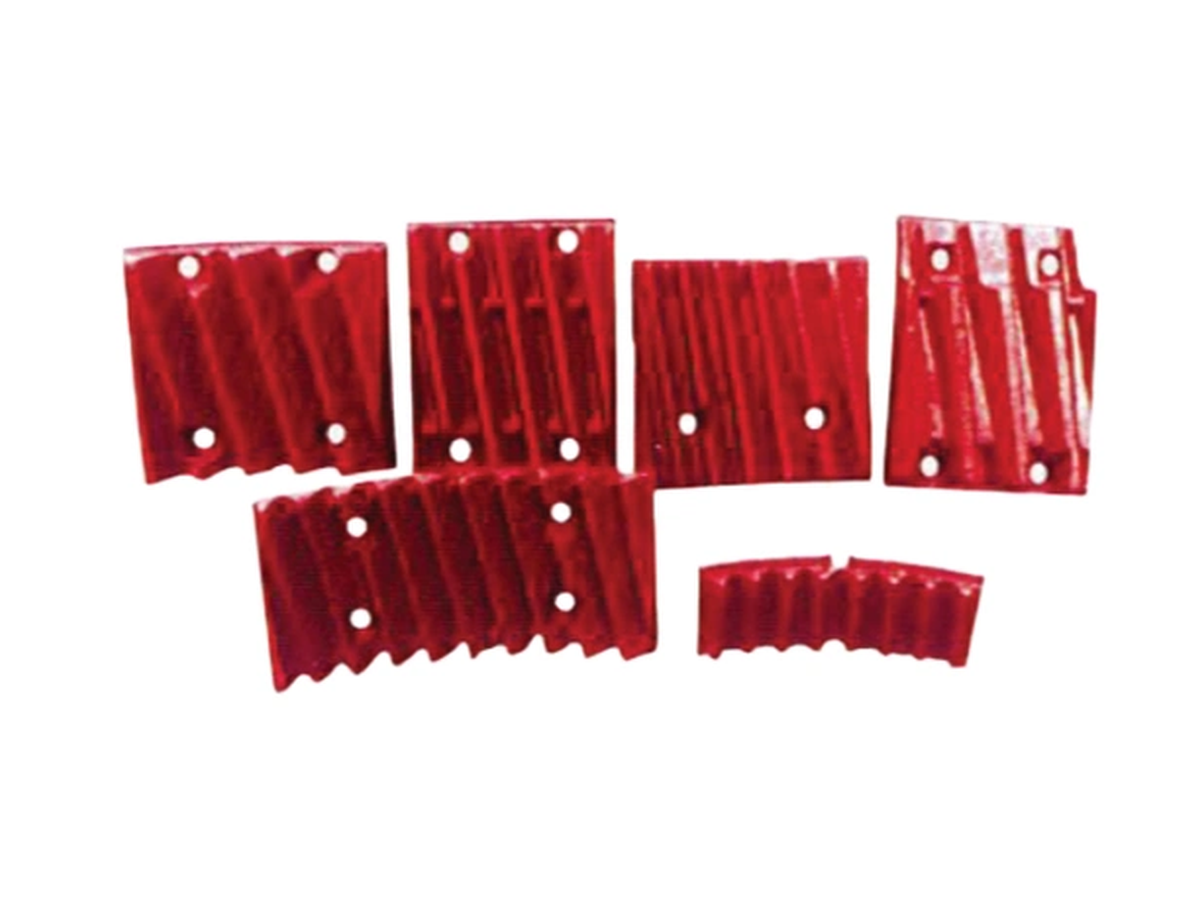
The crusher view illustrates wear-intensive machinery service. Match the liner form, fixing arrangement, feed material and impact conditions.
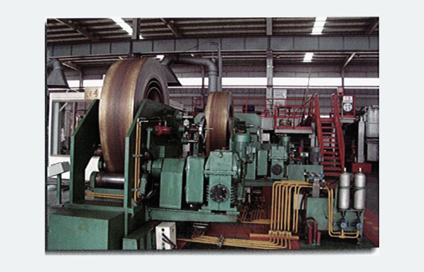
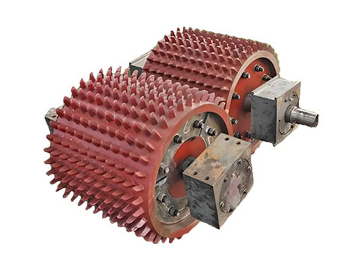
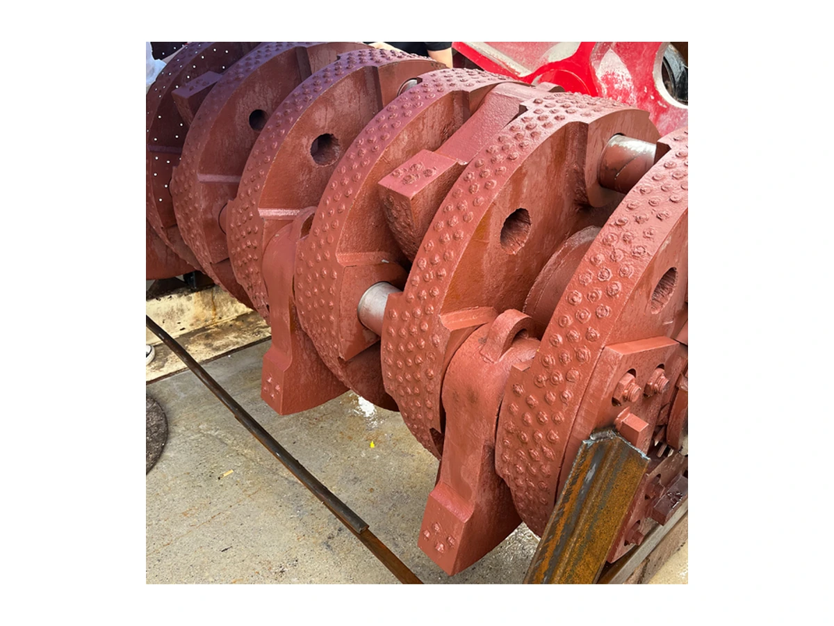
The machinery photo illustrates a second service environment. Drawings, mounting dimensions and actual loads remain the basis for replacement selection.
Equipment photographs show application context only; the supply scope on this page is the listed tooling or components, not complete machines.
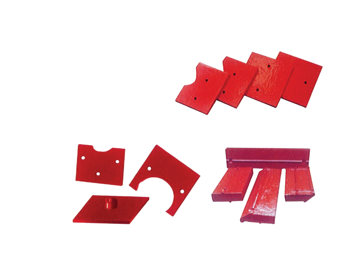
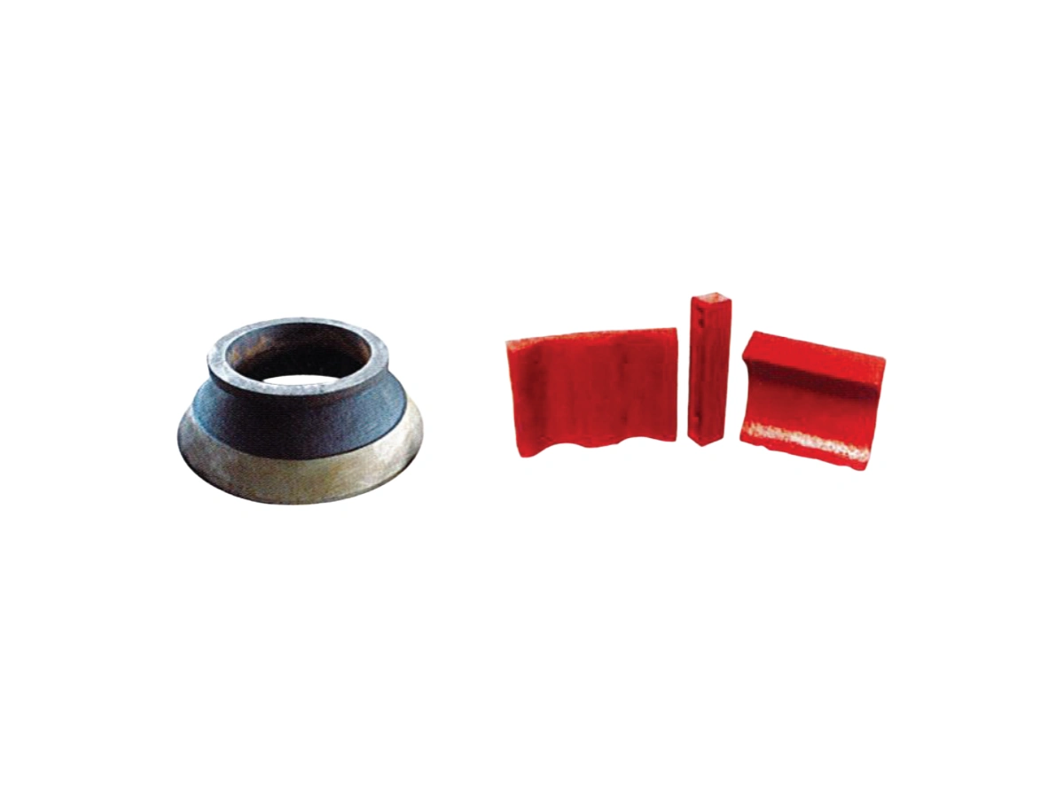
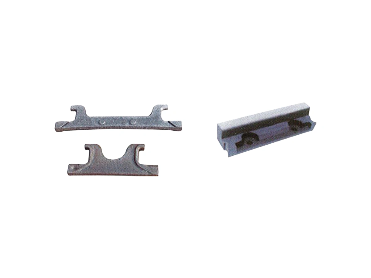
The range covers wear plates, liner forms, mounting components and shaped metal parts for mining and metallurgical machinery. Component geometry and the contact environment define the replacement requirement.
Material, dimensional tolerances and acceptance requirements are reviewed for the actual service conditions. Send the mounting geometry and wear history to help define a suitable replacement.
Specify equipment zone, contacting material, particle size and impact direction, marking working and fixing surfaces. Similar-looking liners in different positions still need separate review of mounting and material-contact conditions.
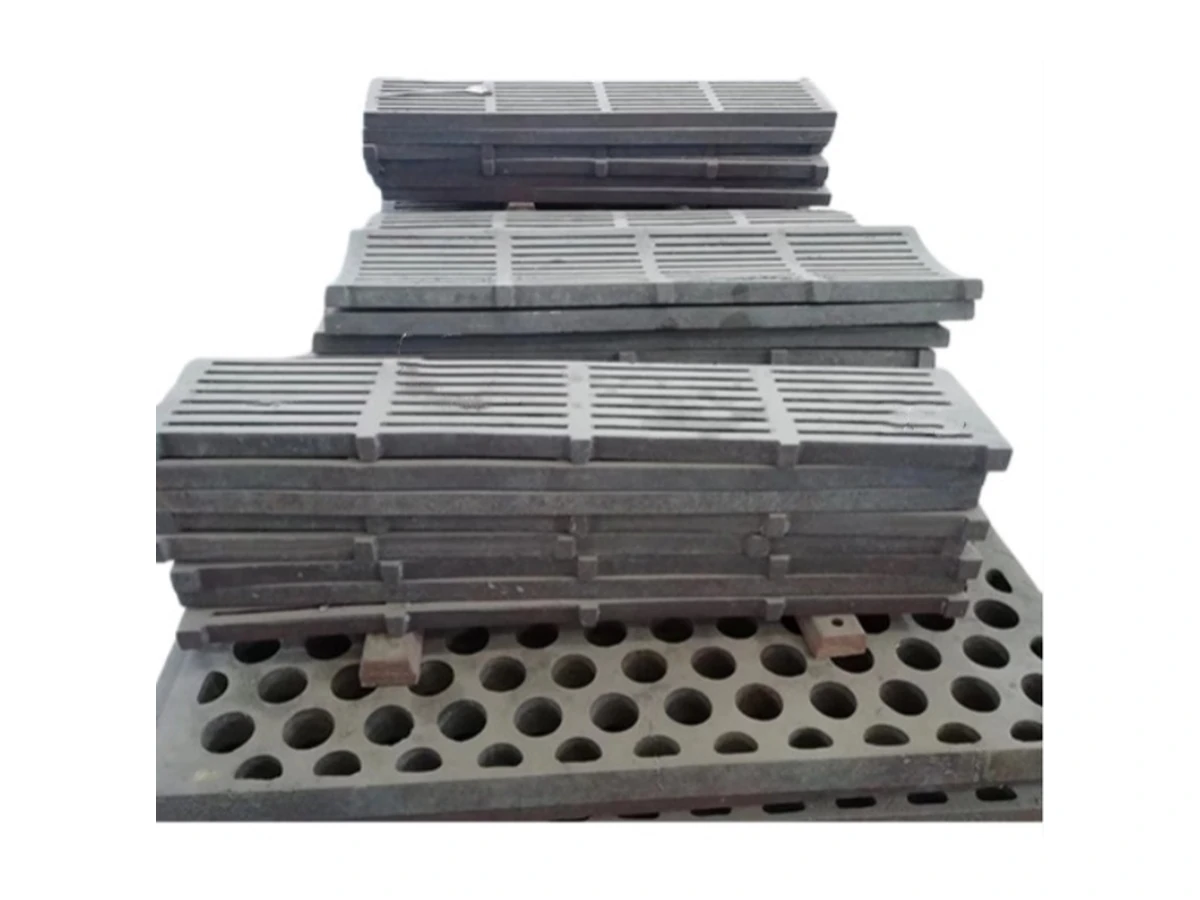
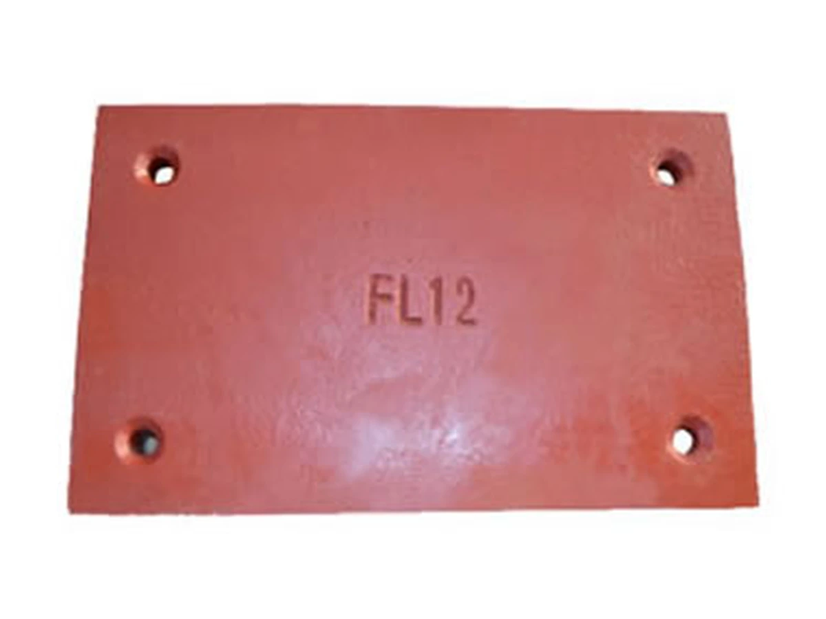
State whether the plate faces sliding contact, flowing material or another task, with boundaries, holes and adjacent-part layouts. Review equipment space and fixing before considering local thickness or profile changes.
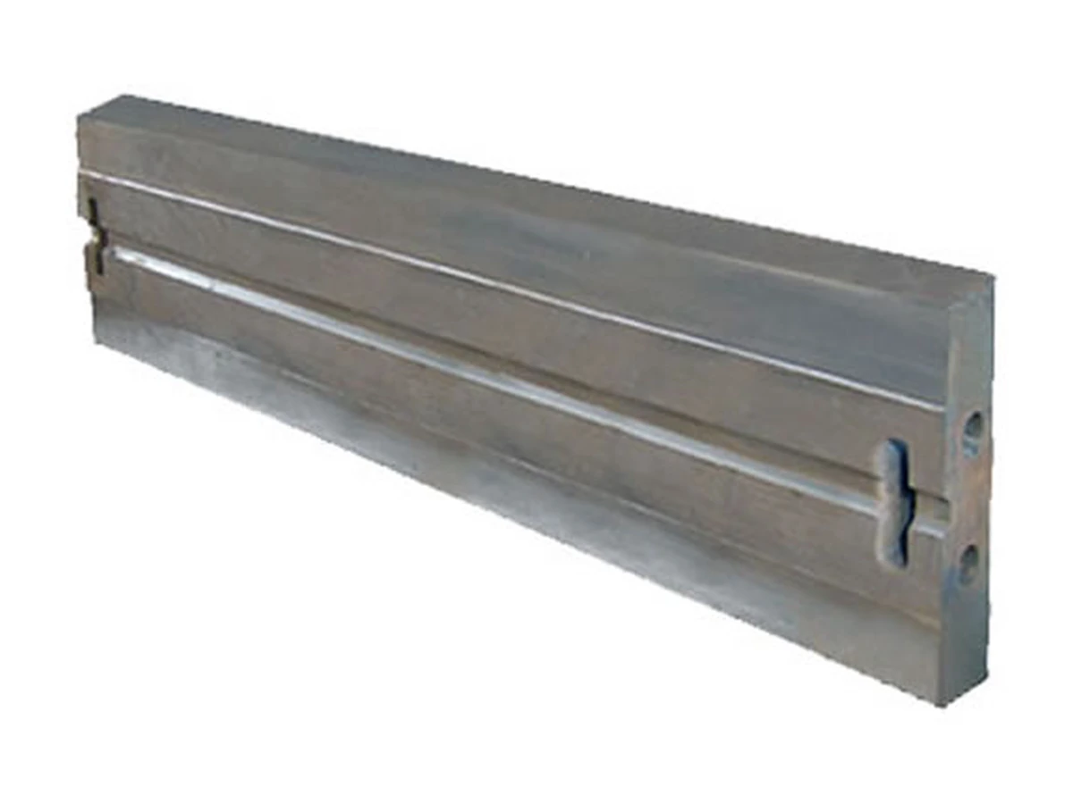
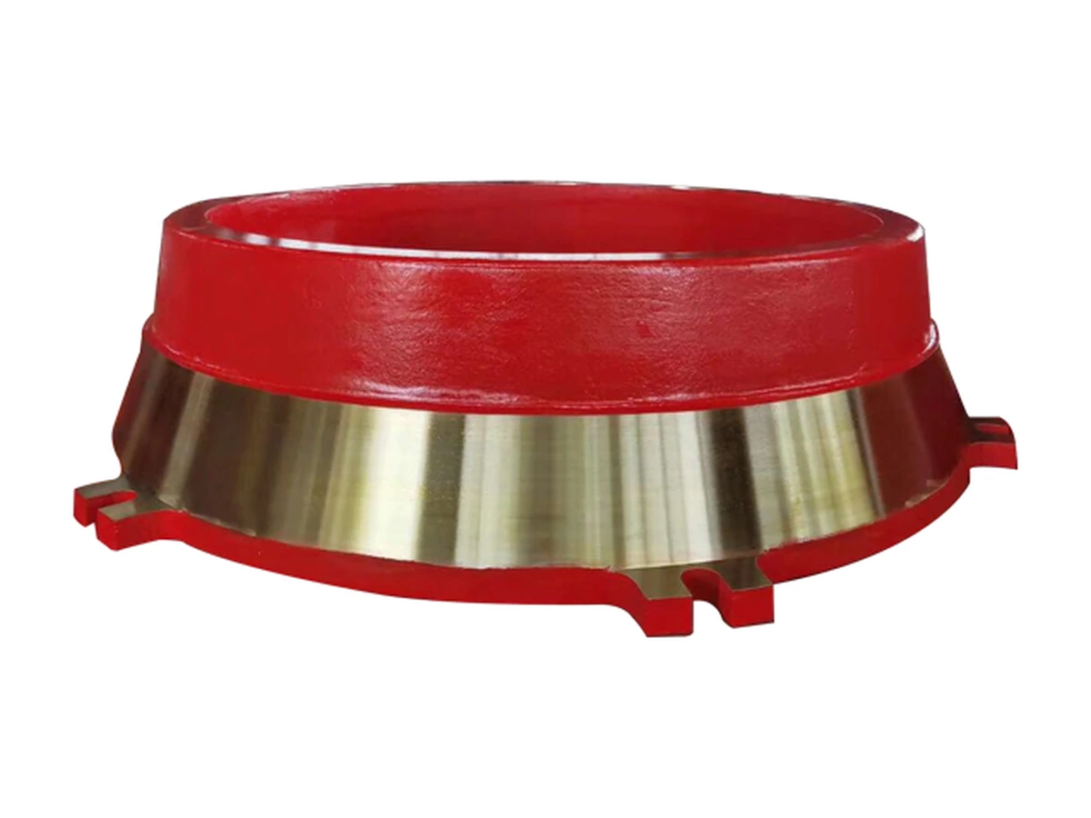
For grooved, shouldered or ring-shaped parts, define actual function, loading and temperature. Appearance does not establish load-bearing use; review support, location and contact relationships from drawings and assembly position.
Product images are for reference. Final dimensions, materials and acceptance criteria are subject to the confirmed drawing and quotation.
Click an image to view product details.
Share the information available using the checklist below to help us review the product against your application. If a complete drawing is not available, start with clear photographs and known dimensions.
The button below opens an email with a product-specific checklist. Fill in the details you know and attach drawings or photographs in your email client.
Email a technical enquiryInformation is for initial review, not a commitment on compatibility, supply or performance. Final materials, geometry, configuration, lead time and acceptance requirements are subject to the confirmed drawing and quotation.
Clarify the operating conditions and interfaces before deciding on materials, geometry or configuration.
Images support initial shape identification, but position, fixing, full dimensions and material duty are also required. Similar appearance does not establish function; provide measured original-part information or verifiable drawings.
Start with retained fixing faces, holes, slots, adjacent parts and installation photographs, recording unworn reference dimensions. The original working profile needs further verification rather than copying the worn shape directly.
These observations may involve different loading and contact factors. Record locations, timing, material and unusual events separately. Retain the parts and provide fixing details before discussing structure or material selection.
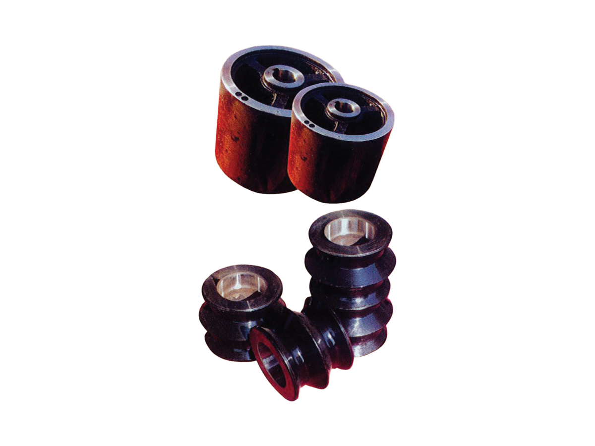
Wear-duty rolls, guide components and hardfaced parts for demanding service.
View product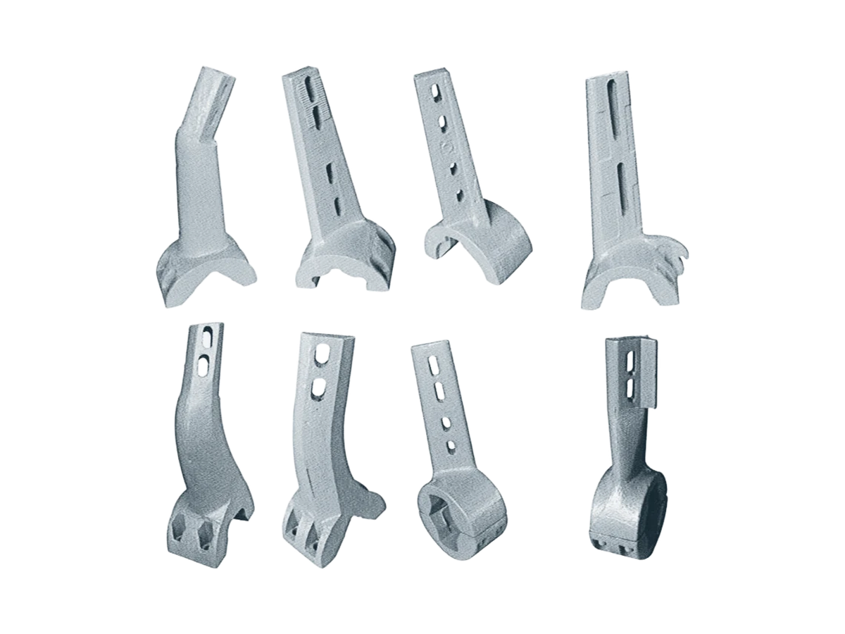
Mixing arms, wear plates and shaped replacement parts for plant machinery.
View product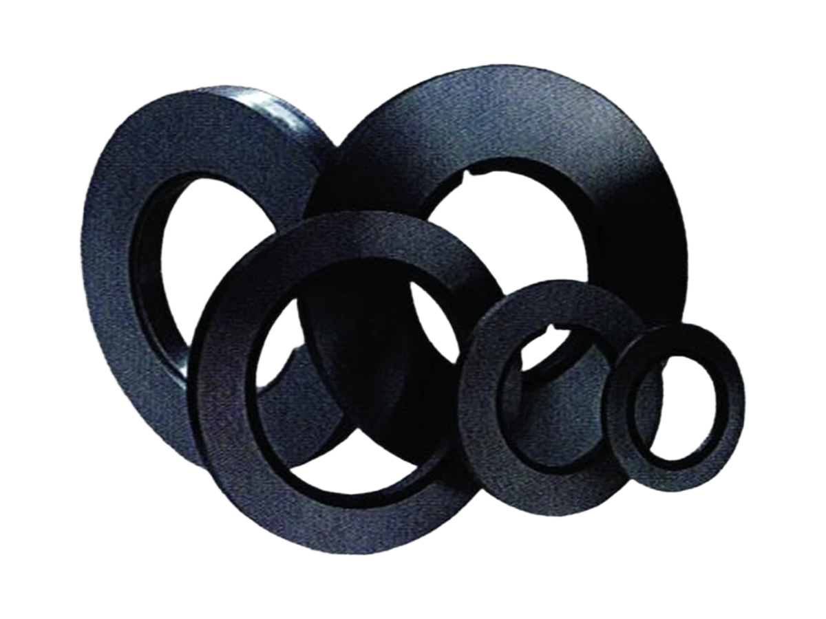
Precision circular knives for coil slitting and edge trimming.
View productShare the operating conditions and quantity so we can define the next step.