
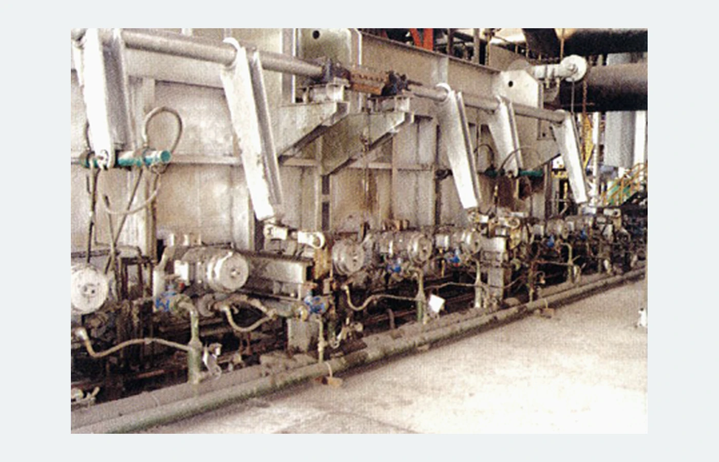
Heating-furnace material handling
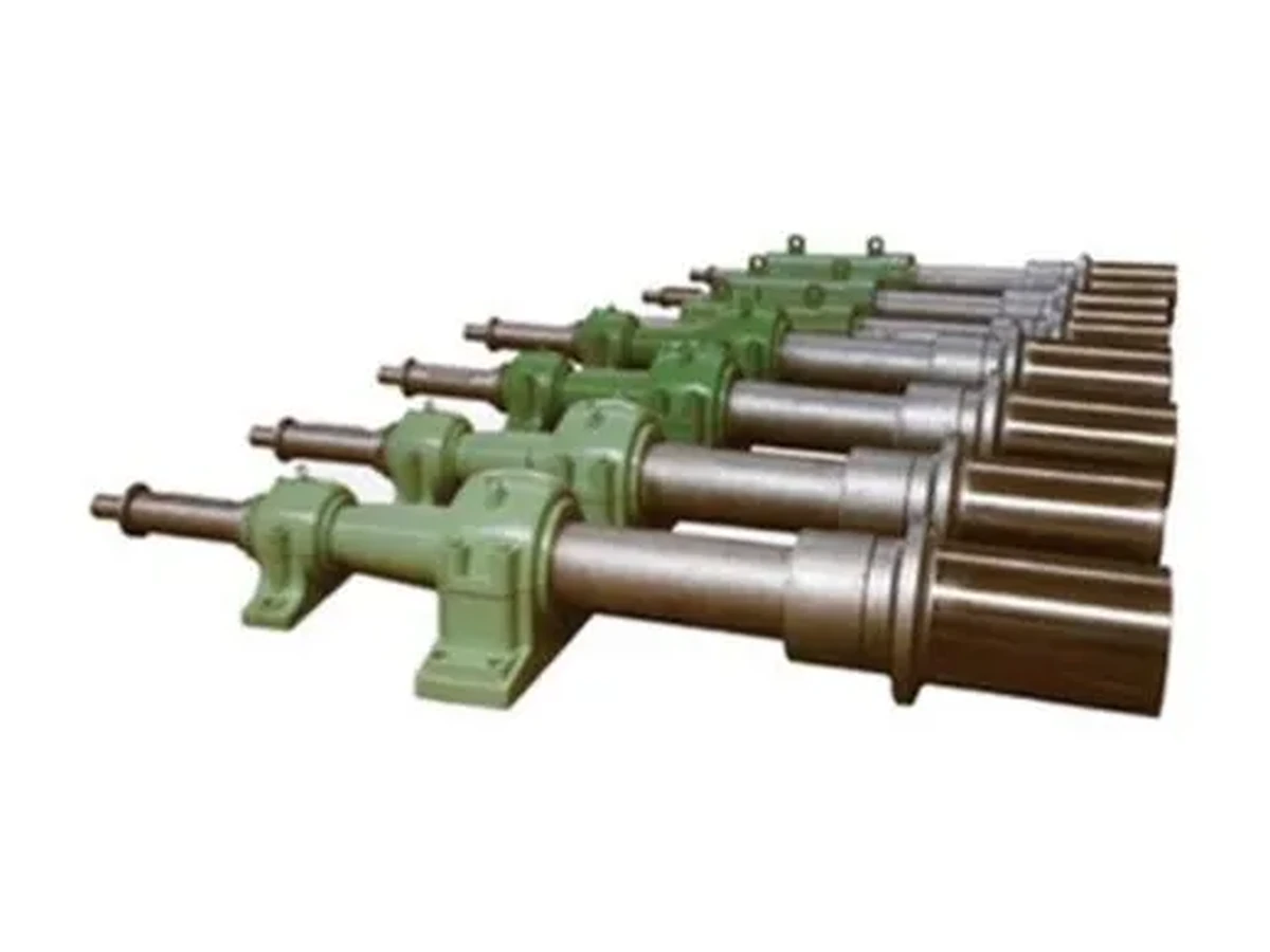
The furnace-side equipment illustrates installation context. Check support positions, shaft and sleeve fit, temperature and cooling arrangements for the assembly.
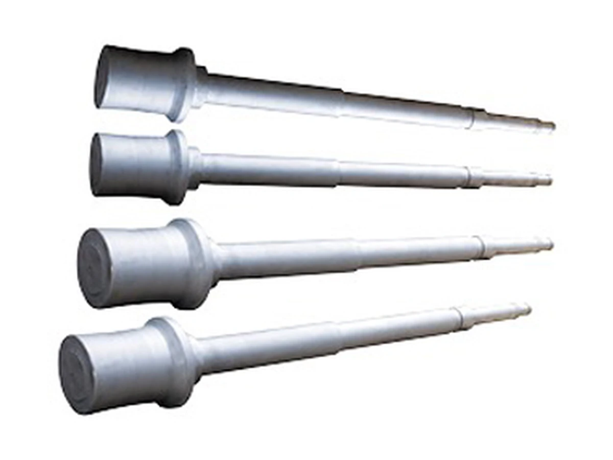
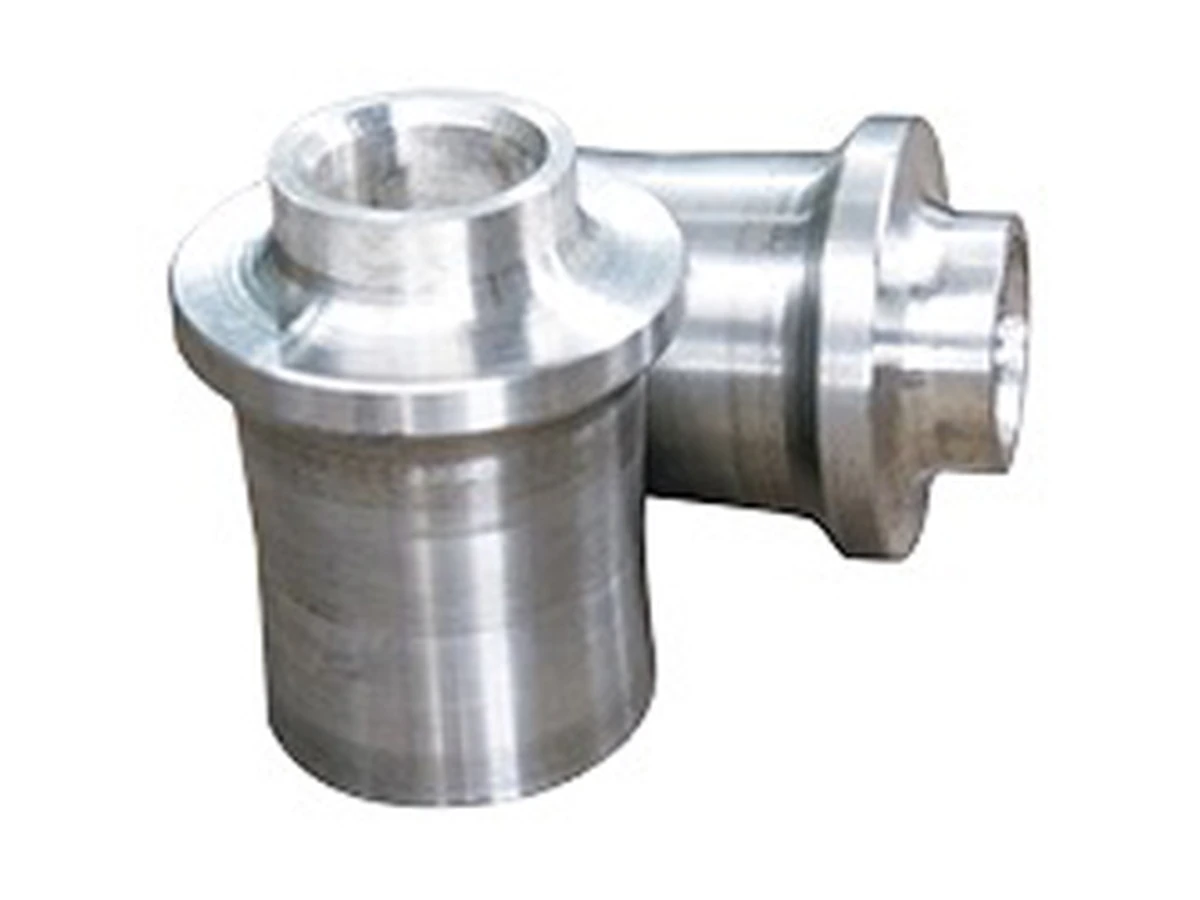
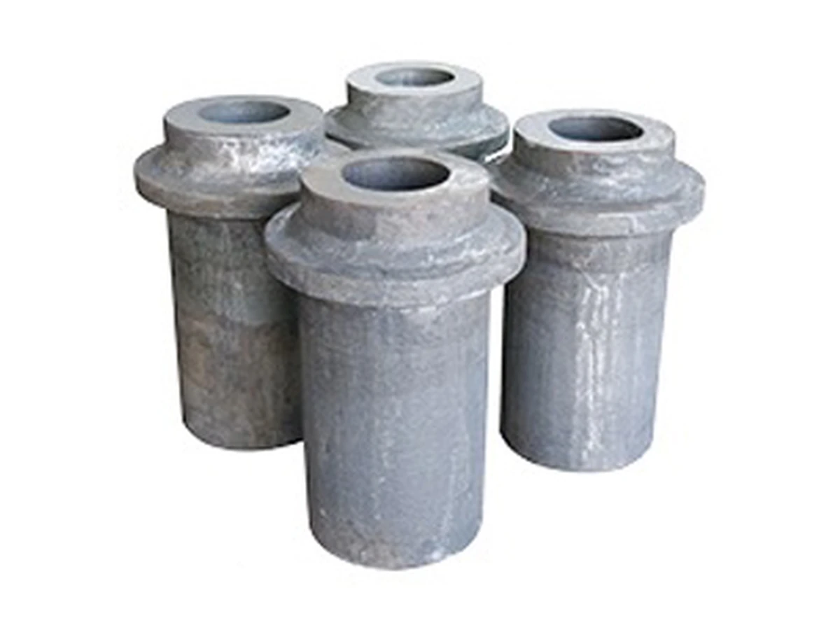
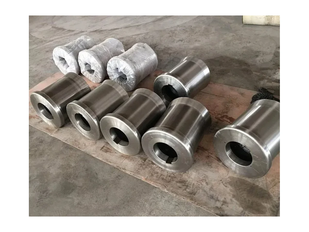
Furnace cantilever rolls handle material at heating-furnace feed and discharge positions in rolling applications. The shaft, sleeve and support arrangement form a furnace-side working assembly. Selection should review overhang, load position, actual temperatures and cooling interfaces together, relating the working end to the external installation. It is also important to define whether the enquiry concerns a complete assembly or individual replacement components, since a local component photograph does not describe the full arrangement.
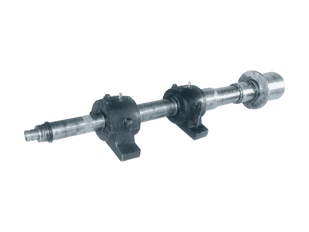
The furnace-side equipment illustrates installation context. Check support positions, shaft and sleeve fit, temperature and cooling arrangements for the assembly.
Equipment photographs show application context only; the supply scope on this page is the listed tooling or components, not complete machines.
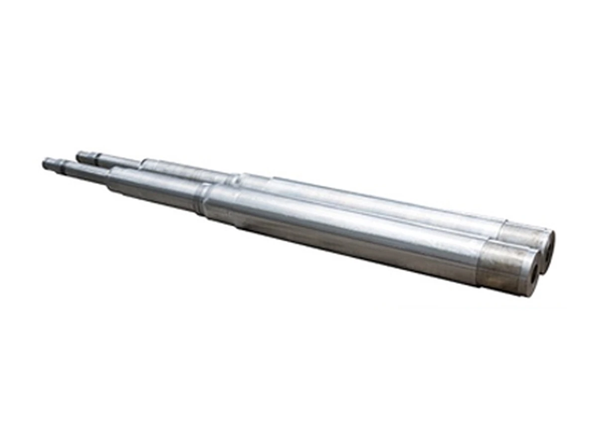
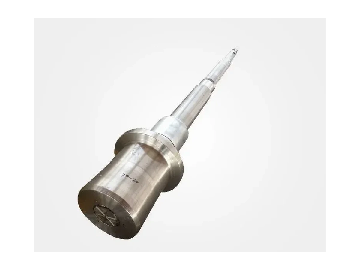
Furnace cantilever rollers are components for heating-furnace material handling. Selection must account for heat and continuous service.
Assembly layout, shaft and sleeve fit, support positions and any cooling connections must be reviewed against the existing installation. The furnace photographs illustrate the application; complete furnaces are not offered through this product page.
Describe workpiece dimensions, transfer or roller-table interfaces and load position. Include the furnace-side boundary and support datums on installation drawings so overhang and available space can be reviewed.
Record where hot material contacts the roll, dwell conditions, transfer cycle and cooling. Furnace set temperature should not be treated as the actual temperature of every component in the roll assembly.
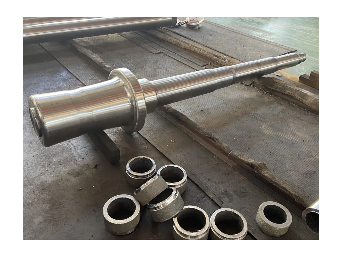
Identify retained components, their dimensions and condition, with sleeve connections and location details. Individual replacements still need review within the complete assembly, including fits and installation sequence.
Product images are for reference. Final dimensions, materials and acceptance criteria are subject to the confirmed drawing and quotation.
Click an image to view product details.
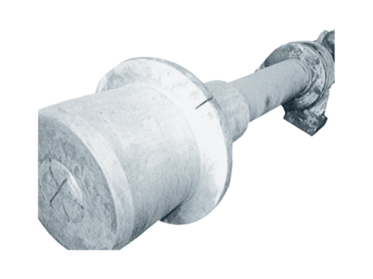
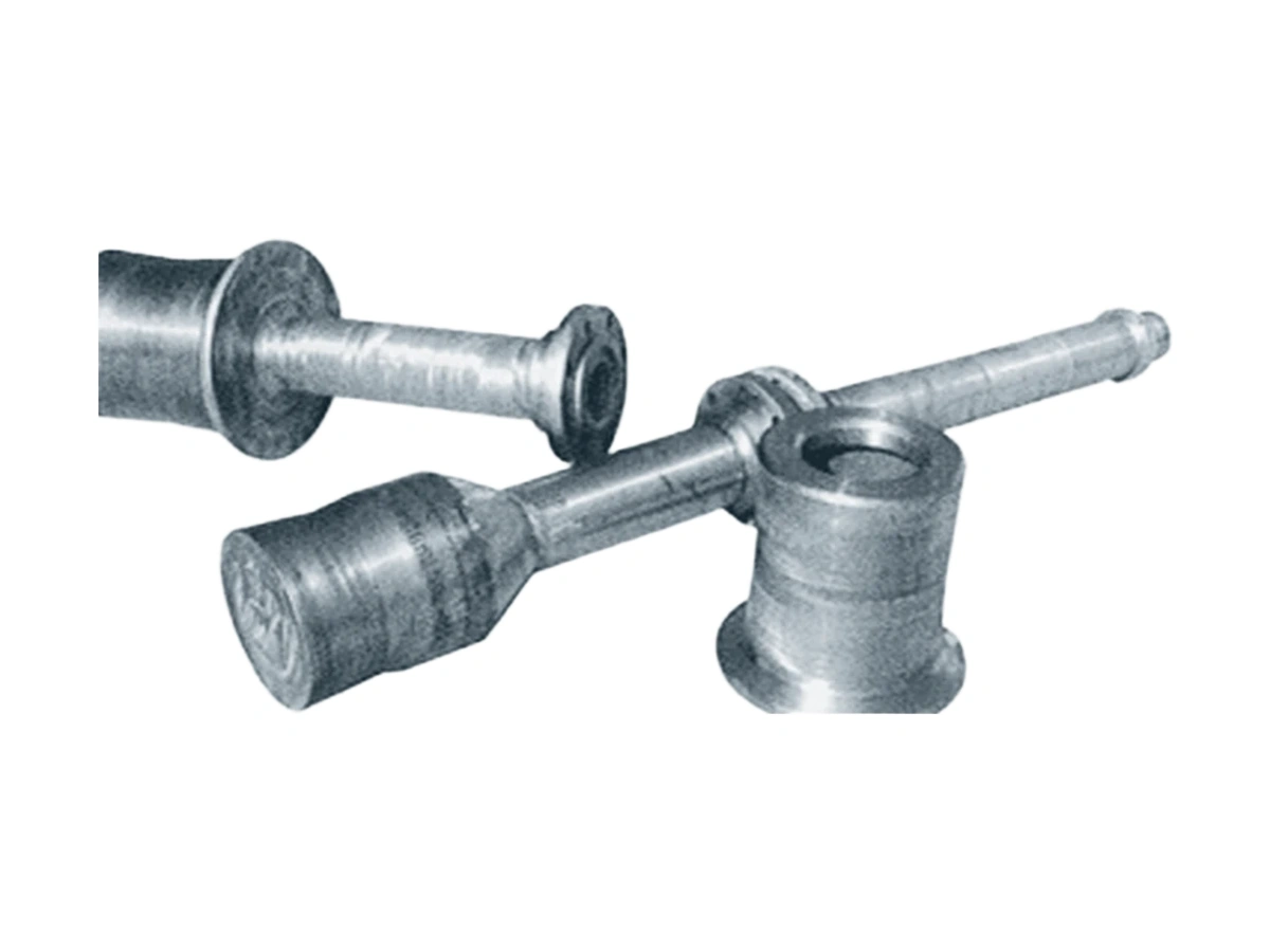
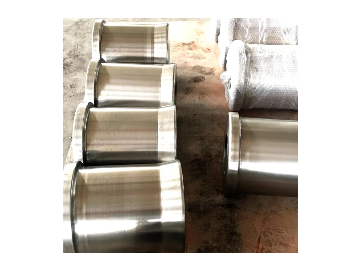
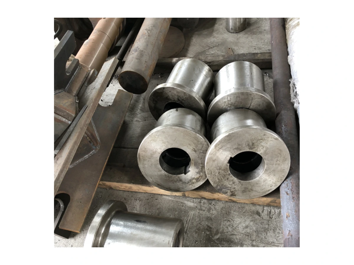
Share the information available using the checklist below to help us review the product against your application. If a complete drawing is not available, start with clear photographs and known dimensions.
The button below opens an email with a product-specific checklist. Fill in the details you know and attach drawings or photographs in your email client.
Email a technical enquiryInformation is for initial review, not a commitment on compatibility, supply or performance. Final materials, geometry, configuration, lead time and acceptance requirements are subject to the confirmed drawing and quotation.
Clarify the operating conditions and interfaces before deciding on materials, geometry or configuration.
No. Actual component temperatures also depend on material contact, cooling, overhang and loading. Provide operating records and installation drawings so material and temperature suitability can be reviewed for the assembly.
Check shaft dimensions, location, fit-surface condition and assembly sequence. Disassembly photographs and measured sketches can start the review, but critical connections need confirmation rather than selection from sleeve OD alone.
Record damage locations, material dwell, startup/shutdown events and cooling changes. Add support layout and part photographs. Bending or cracking may involve several factors and requires review of the site information.
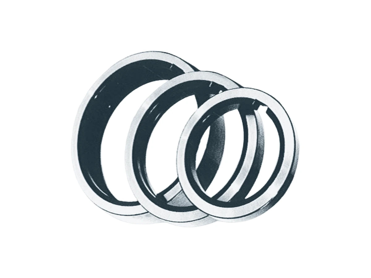
Cutter shims, locating bushes and spacer sets for accurate slitting setups.
View product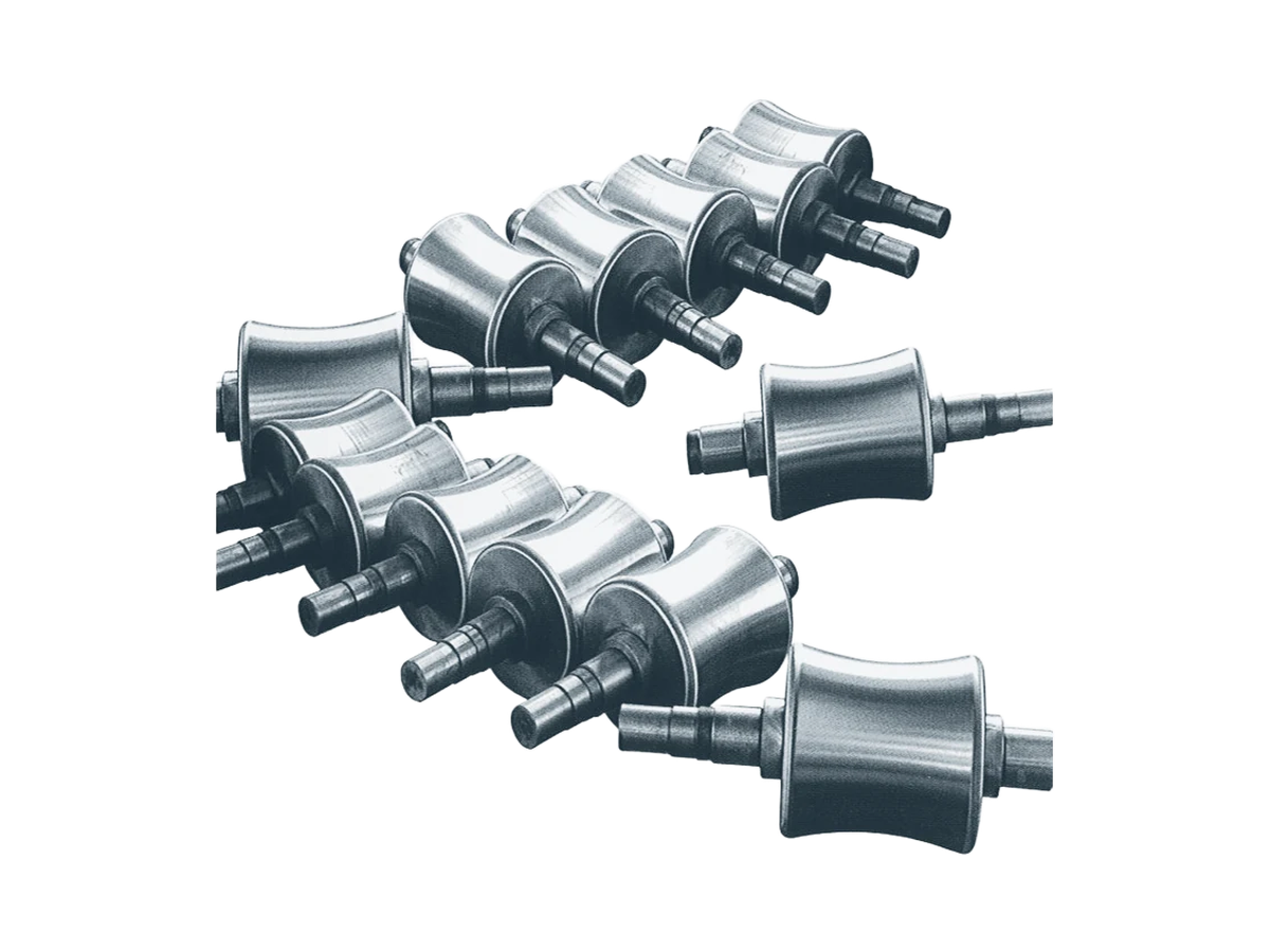
Straightening, carrying and profile rolls for industrial processing lines.
View product
Precision circular knives for coil slitting and edge trimming.
View productShare the operating conditions and quantity so we can define the next step.